Top 3 safety hazards to avoid for PV solar installations
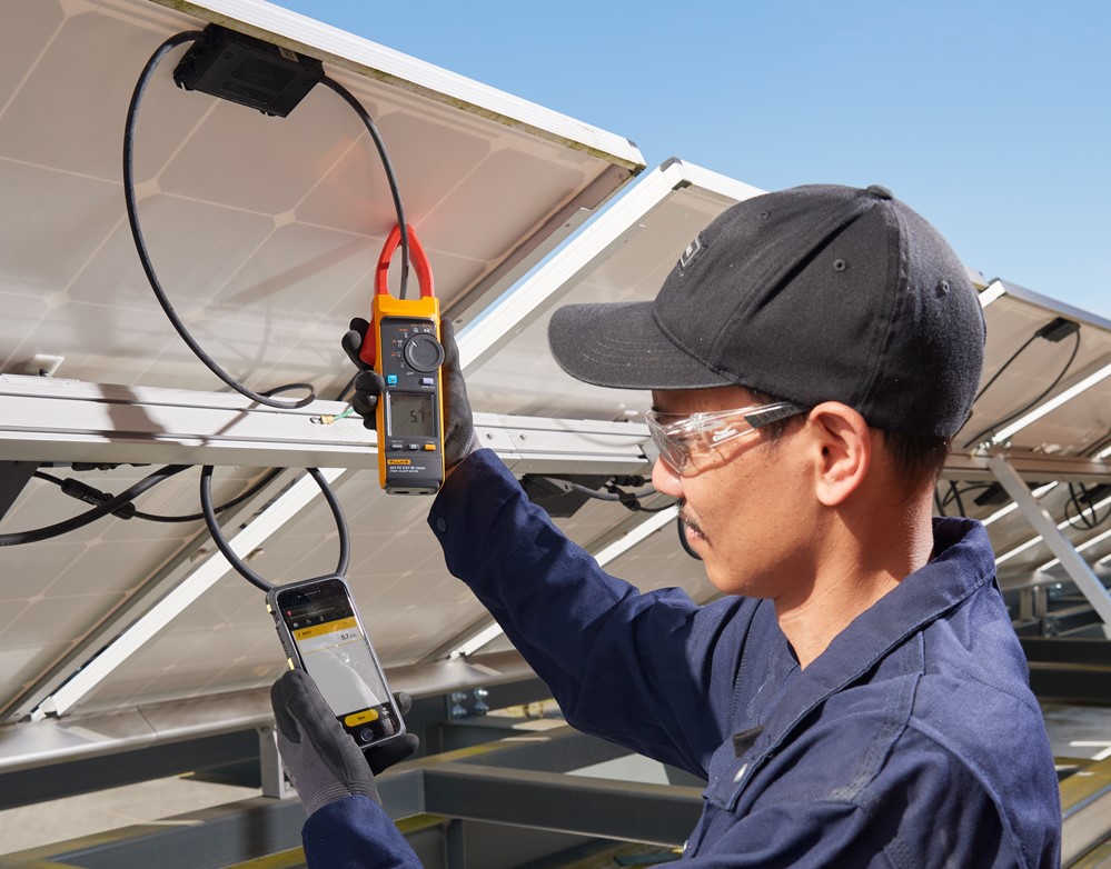
Safety levels during solar panel commissioning and installation have been strengthened substantially by the world’s first CAT III 1500 V true-RMS solar clamp meter
Renewable energy is one of the fastest-growing markets in the world – recent trends show solar installations have doubled within the last year and are expected to double again by 2030. Such rapid expansion is accelerating the search for ways to reduce risks associated with commissioning and installing photovoltaic (PV) systems. The resulting demand for highly accurate hand-held devices capable of carrying out safe and reliable measurements in these applications has now been met with the introduction of the world’s first CAT III 1500 V true-RMS solar clamp meter, Fluke’s 393 FC.
In PV applications current is “wild” and not limited by electronics, therefore choosing the correct solar testing equipment is vital if workers – and the PV system itself – are to be protected against a range of potential electrical hazards.
The easy-to-use Fluke 1625-2 has world-class accessories to speed up set-up and test time, and the tester indicates which stakes or clamps to connect for each test. The large rotary switch and buttons are easy to operate, even with a gloved hand. Up to 1,500 records can be stored, and accessed easily via the USB port.
No. 1 Electrocution
The Fluke 393 FC helps to protect against the three main electrical hazards – shock or electrocution from energised conductors, arc faults that spark fires and arc flash that leads to explosions. Control measures and best practices that can mitigate these risks are different when working with PV working with any other kind of energy-generating resource. That’s why it’s important that multimeters, test leads and fuses are rated for the application being worked on.
Shock or electrocution from energised conductors can happen when current takes an unintended path through a human body, with lethal results from as little as 50 milliamps (mA) hitting the heart. Electrical shocks are typically caused by faulty insulation of cables and wiring, damaged insulation of safety covers or improper grounding. The main places such conditions exist in a PV system are the combiner box, the equipment grounding conductor, the PV source and output circuit conductors.
No. 2 Arc faults and arc flash
Electrical arc faults that spark fires are high power discharges of electricity between two or more conductors, with the discharge causing heat that can lead to the deterioration or even to burning of wiring insulation. PV systems are particularly vulnerable to arc faults caused by a disruption in conductor continuity or by unexpected current between two conductors, often the result of a ground fault.
Arc flash is a phenomenon of large-scale PV arrays that have medium-to-high voltage levels. Only since large-scale solar energy systems gave been created has arc flash become a DC issue, which is why arc flash hazard risk analysis must now be carried out on DC systems over 120 V. The issue is particularly prevalent when fault-checking in energised combiner boxes, where PV source circuits are used in parallel to increase current, or when carrying out checks on medium-to-high voltage switchgear and transformers. An arc flash happens when there’s a significant level of energy available to an arc fault in DC and AC conductors. The flash emits hot gases and radiant energy that can be around 19,500° C (or four times the temperature of the surface of the sun). The most at-risk set-ups are residential inverters with input voltage up to 500 V and large-scale inverters with up to 1500 V. It’s essential to use a meter that’s rated for the relevant measurement category or CAT rating as well as the application’s voltage level. This is so the unit can cope with average voltage levels and high voltage spikes and transients that are capable of producing shocks or causing an arc flash.
No. 3 Switching to 1500 V
Most major manufacturers of inverters and solar modules are moving from 1000 V systems to 1500 V for greater efficiency. For solar installations, overvoltage category CAT III 1500 V systems are being more widely used and CAT III and CAT IV equipment is essential for PV systems at high altitudes. Only the Fluke 393 FC True-RMS Solar Clamp Meter matches the insulation demands of such CAT III environments.
Polarity functions and audible and visual polarity checks are crucial when commissioning a new site, whether at the combiner box level or inverter level. With a DC polarity check, it’s easy to spot if the polarity of strings has been reversed accidentally, avoiding the risk of fires at the combiner box as well as damage to the equipment and danger to personnel.
Safe, reliable and rugged
All test results are logged and reported via the Fluke Connect software that comes with the Fluke 393 FC true-RMS Solar Clamp Meter. Using just a phone, engineers can make and save measurements quickly, with the phone recording for 10 minutes and reporting readings to colleagues. Capable of measuring and recording up to two weeks, this safe, reliable and rugged meter also comes with an 18-inch iFlex flexible current probe for extended AC measurements up to 2500 amps. Test leads are also rated to CAT III 1500 V DC.